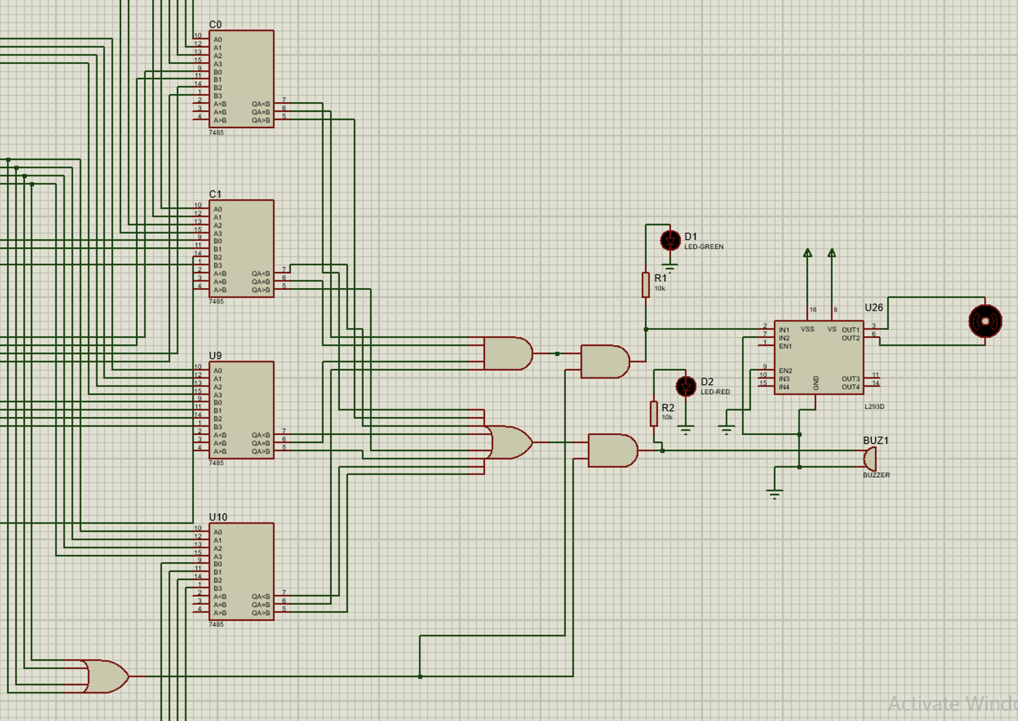
lock System With Keypad 9 Steps Circuit Diagram password based door locking system:keypad input arduino | keypad lock with arduino | arduino door lock:the following video shows how to make a password based The numbers that will represent each button are from 1-9. The keypad will have outputs in a 4-bit format. For example, when you press the '7' button then the output from OR gates will be '0111'. Construct the keypad by following the attached picture above. After the keypad is constructed, connect the outputs from the OR gates into 4043 IC. 555 Timer electronic Door lock; RFID Door lock system using Arduino; Before building our password door locking project, first, we need to collect the required components and then go ahead and follow the step by step building process. Arduino Code for Digital Keypad Door Lock. The design files are also shown in the picture below.
Introduction A 4×4 keypad module is an electronic input device commonly used in various applications for interfacing with microcontrollers and other digital systems. It consists of a grid of buttons arranged in a 4×4 matrix, resulting in a total of 16 buttons. Each button corresponds to a specific alphanumeric character, symbol, or command. Working Principle: A technique called "keypad
Arduino Activated Safe Lock System : 6 Steps Circuit Diagram
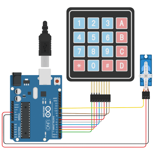
This is a door lock security system made with Arduino. Door Lock System with Arduino. interfacing_keypad_with_arduino_8xDFWS5uS3.JPG. lcd_with_arduino_ZHuuxD17fT.JPG. lcd_with_arduino_ZHuuxD17fT.JPG. CIRCUIT DIAGRAMS. CIRCUIT DIAGRAMS. Comments. Only logged in users can leave comments. In this instructable, I will be showing you how to create an Arduino controlled and activated safe lock mechanism. The system functions the same way a normal safe mechanism would, you enter a 4 digit code onto the keypad attached to the Arduino, if you enter the correct code, the Arduino will then send a signal to the servo motor to start
Tinkercad is a free web app for 3D design, electronics, and coding. We're the ideal introduction to Autodesk, a global leader in design and make technology. Follow Us

Arduino Digital Code Lock Project Using Matrix Keypad Circuit Diagram
𝗩𝗶𝗱𝗲𝗼 𝗗𝗲𝘀𝗰𝗿𝗶𝗽𝘁𝗶𝗼𝗻:In this project, we will make a Password-Based Door Lock Security System using Arduino, a keypad, a servo motor, an LCD, an
